Patent / CN210041834U
Submersible Communication System
An underwater communication system connecting a submersible, a relay buoy, a control terminal and a fibre-optic cable. The design combines optical, wireless and sonar modules to support image and data transmission, control and underwater positioning.
Abstract
English translationThis utility model discloses a submersible communication system comprising a submersible, a control terminal, a relay buoy and a communication cable. The relay buoy contains a power module and optical-fibre communication, wireless communication, main control and sonar modules electrically connected to the power module. The main control module is electrically connected to the optical-fibre communication, wireless communication and sonar modules. The communication cable connects to the optical-fibre communication module inside the relay buoy. The control terminal controls the main control module through the wireless communication module. The utility model addresses real-time underwater image and data transmission and real-time control of the submersible.
Patent Drawings
5 sheets · 8 figuresPublished drawings with English labels. Select a sheet to enlarge it here.
 Enlarge
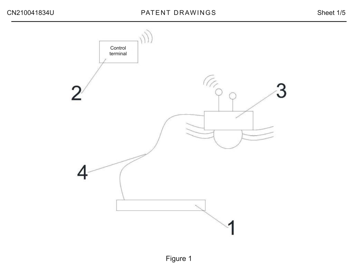
Figure 1 is a structural view of the submersible communication system.
 Enlarge
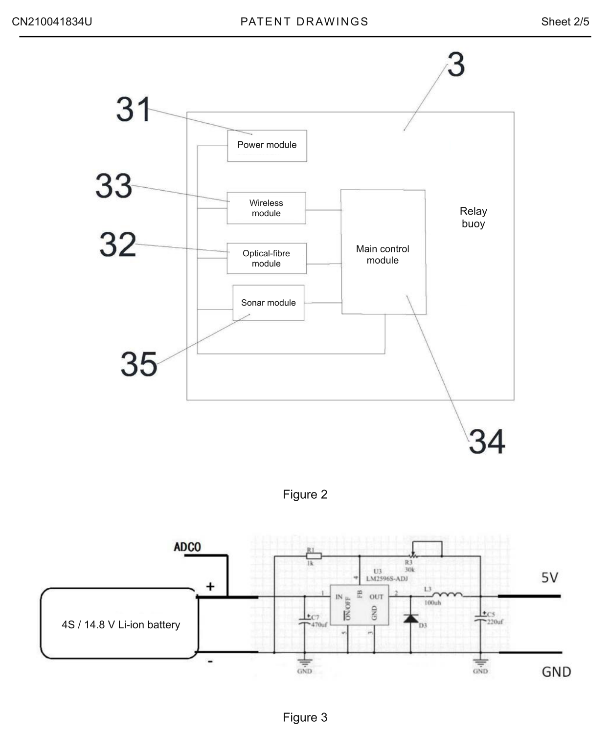
Figure 2 is a system diagram of the relay buoy in the submersible communication system.
Figure 3 is a circuit diagram of the power module.
 Enlarge
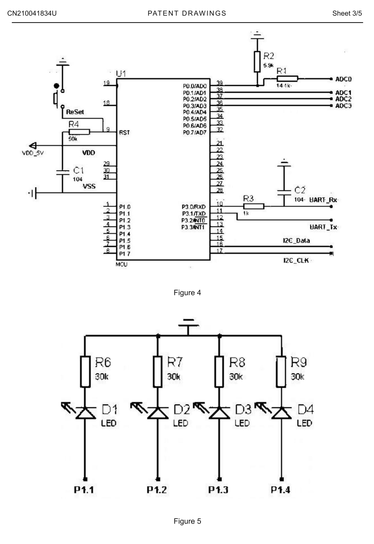
Figure 4 is a circuit diagram of the main control module.
Figure 5 is a circuit diagram of the operating-status indicator lights.
 Enlarge
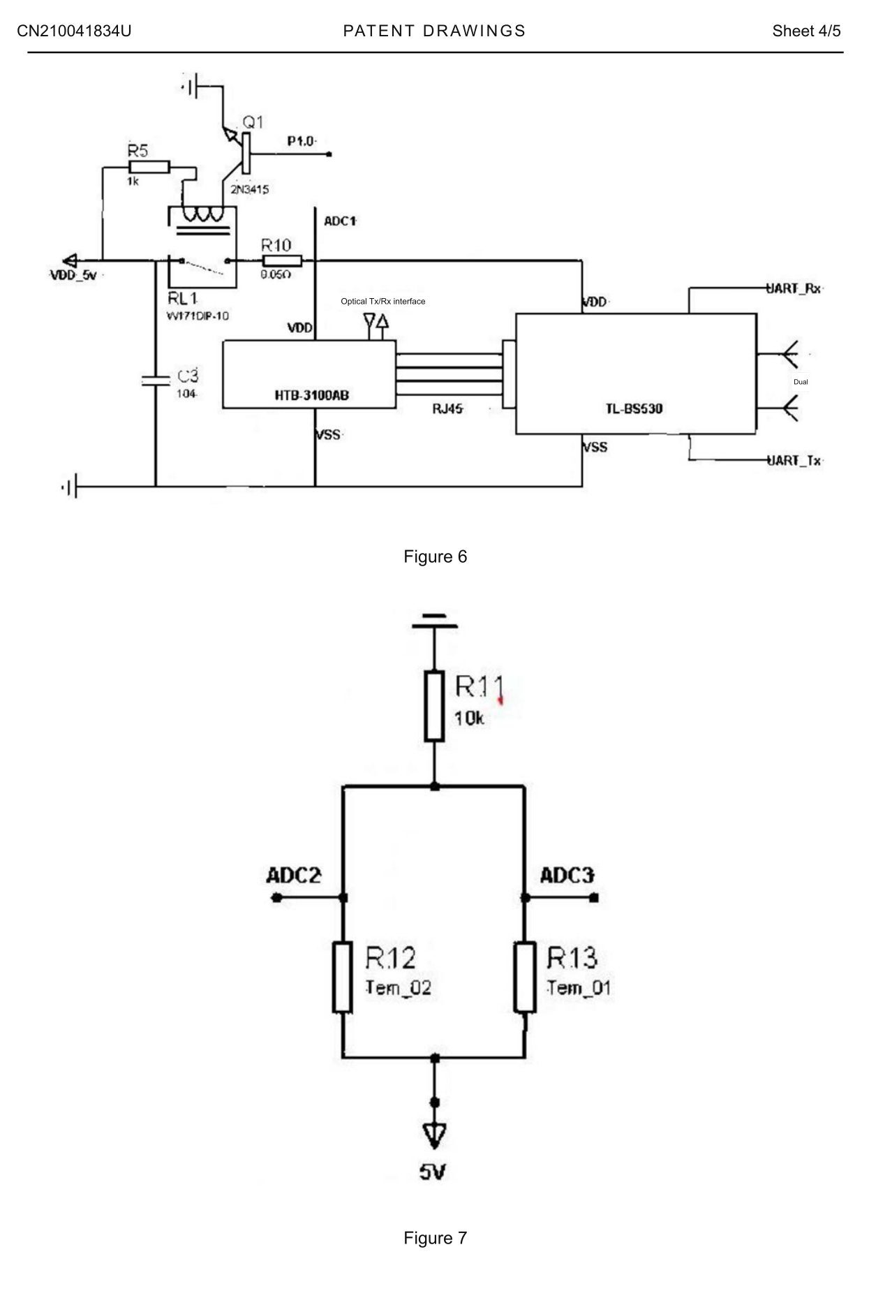
Figure 6 is a circuit diagram of the optical-fibre communication and wireless communication modules.
Figure 7 is a circuit diagram for monitoring operating temperature.
 Enlarge
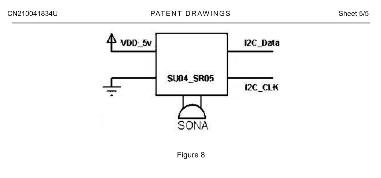
Figure 8 is a circuit diagram of the sonar module.
Claims
5 claims · English translation- 1. A submersible communication system comprising a submersible, a control terminal, a relay buoy and a communication cable, wherein the relay buoy contains a power module and optical-fibre communication, wireless communication, main control and sonar modules electrically connected to the power module; the main control module is electrically connected to the optical-fibre communication, wireless communication and sonar modules; the communication cable connects to the optical-fibre communication module inside the relay buoy; and the control terminal controls the main control module through the wireless communication module.
- 2. The submersible communication system according to claim 1, wherein the power module uses an LM2596S voltage-regulation circuit.
- 3. The submersible communication system according to claim 1, wherein the wireless communication module is a TL-BS530 wireless module.
- 4. The submersible communication system according to claim 1, wherein the communication cable is an optical-fibre cable.
- 5. The submersible communication system according to claim 1, wherein the sonar module is positioned below the relay buoy.
Description
Complete specification · English translationTechnical field
This utility model relates to submersible communication technology, and in particular to a submersible communication system.
Background
Wireless communication has difficulty penetrating water, making control and data transmission major challenges for unmanned submersibles. Conventional underwater methods have limitations: sonar communication penetrates well but has a low data rate, making real-time image transmission difficult, and its coverage is limited; very-long-wave radio communication has the widest coverage, but the equipment is very large and expensive and has poor penetration; connecting a submersible by a communication cable enables stable, very-high-speed transmission but over a short distance. Given these technical barriers and the limitations of conventional methods, a new communication approach is needed to obtain real-time underwater images and data and control the submersible in real time.
Technical solution
To overcome the above shortcomings of the prior art, this utility model provides a submersible communication system that addresses real-time underwater image and data transmission and real-time control of the submersible.
The technical solution is a submersible communication system comprising a submersible, a control terminal, a relay buoy and a communication cable. The relay buoy contains a power module and optical-fibre communication, wireless communication, main control and sonar modules electrically connected to the power module. The main control module is electrically connected to the optical-fibre communication, wireless communication and sonar modules. The communication cable connects to the optical-fibre communication module inside the relay buoy. The control terminal controls the main control module through the wireless communication module.
In a preferred arrangement, the power module uses an LM2596S voltage-regulation circuit.
In a preferred arrangement, the wireless communication module is a TL-BS530 wireless module.
In a preferred arrangement, the sonar module is positioned below the relay buoy.
In a preferred arrangement, the communication cable is an optical-fibre cable.
Compared with the prior art, this utility model provides the following technical effects:
The relay buoy connects to the submersible by a communication cable and sends communication signals to the control terminal through its wireless communication module. This enables real-time acquisition of underwater images and data and remote operation of the submersible, reducing control difficulty, increasing flexibility and extending its applications. A sonar module on the relay buoy uses echolocation to obtain accurate underwater position data for the submersible and sends it to the control terminal. If the submersible fails underwater, the relay buoy and communication cable also facilitate its recovery.
Description of drawings
Figure 1 is a structural view of the submersible communication system.
Figure 2 is a system diagram of the relay buoy in the submersible communication system.
Figure 3 is a circuit diagram of the power module.
Figure 4 is a circuit diagram of the main control module.
Figure 5 is a circuit diagram of the operating-status indicator lights.
Figure 6 is a circuit diagram of the optical-fibre communication and wireless communication modules.
Figure 7 is a circuit diagram for monitoring operating temperature.
Figure 8 is a circuit diagram of the sonar module.
Reference numerals: 1 — submersible; 2 — control terminal; 3 — relay buoy; 4 — communication cable; 31 — power module; 32 — optical-fibre communication module; 33 — wireless communication module; 34 — main control module; 35 — sonar module.
Detailed embodiments
Specific embodiments of this utility model are described below with reference to the accompanying drawings. These descriptions are intended to assist understanding and do not limit the utility model. The technical features of the embodiments described below may be combined, provided that they do not conflict with one another.
As shown in Figure 1, the submersible communication system comprises a submersible 1, a control terminal 2, a relay buoy 3 and a communication cable 4. The relay buoy 3 contains a power module 31 and optical-fibre communication, wireless communication, main control and sonar modules 32–35 electrically connected to it. The main control module 34 is electrically connected to modules 32, 33 and 35. Cable 4 connects to the optical-fibre communication module 32 inside the buoy 3. The control terminal 2 controls the main control module 34 through the wireless communication module 33.
The communication system for submersible 1 combines the stability, high speed and real-time capability of cable communication with the broad coverage of wireless communication and the penetration and underwater-positioning capability of sonar communication.
The body of relay buoy 3 can float entirely on the water surface and is independently powered by an internal lithium battery. An optical-fibre cable connects it to submersible 1 for data communication. Cable 4 is buoyant, allowing excess cable to float on the surface and reducing underwater entanglement. The main control module 34 in the buoy parses and stores optical-fibre signals, then sends them to control terminal 2 through wireless module 33. Control signals from terminal 2 travel in the opposite direction along the same link, relayed by buoy 3 to submersible 1. Sonar module 35 on the buoy uses echolocation to obtain accurate underwater position data and sends it to terminal 2. Submersible 1 can tow buoy 3 to the area where underwater work is required.
In a preferred arrangement, power module 31 uses an LM2596S voltage-regulation circuit.
In a preferred arrangement, wireless communication module 33 is a TL-BS530 wireless module.
In a preferred arrangement, sonar module 35 is positioned below relay buoy 3.
In a preferred arrangement, the communication cable is an optical-fibre cable.
As shown in Figures 3–8:
1. A 4S lithium battery pack supplies power to the system. An LM2596S voltage-regulation circuit provides a stable 5 V system output, at which all other system components and modules operate.
2. The main MCU performs system-management functions and executes commands from the user terminal. Pressing the ReSet button or reconnecting the power resets its program.
3. The main MCU obtains system-status information through four analogue-to-digital conversion ports: ADC0 monitors the battery-pack voltage; ADC1 monitors the operating current of the communication module; and ADC2 and ADC3 monitor two thermistors to obtain the system-board and air temperatures respectively.
4. The main MCU exchanges data with the TL-BS530 wireless module through a set of serial communication ports to receive user-terminal commands and upload system-status data. Data are uploaded automatically every 1 s.
5. The main MCU exchanges data with sonar module 35 through a set of I2C ports. The sonar module obtains echolocation data and sends the underwater relative position of submersible 1 to the MCU. Sonar data are acquired every 500 ms.
6. Wireless communication module 33 mainly comprises three module sections. The main MCU controls the module's power-supply relay through port P1.0. The HTB-3100AB optical-fibre communication converter converts between optical-fibre data and standard RJ45 signals. The TL-BS530 wireless module then converts between RJ45 and radio signals to communicate with the user terminal. The optical-fibre converter and wireless module operate automatically when powered.
7. The main MCU controls four LED indicators according to system status: D1 indicates power status; D2 indicates communication-module status; D3 indicates temperature status; and D4 indicates communication between the MCU and the wireless module. A continuously lit operating indicator normally denotes normal operation, while flashing denotes an abnormal condition. For D4, illumination indicates active communication between the MCU and wireless module, so D4 should flash once every 1 s during normal operation.
Compared with the prior art, this utility model provides the following technical effects:
Relay buoy 3 connects to submersible 1 through communication cable 4 and sends signals to control terminal 2 through wireless module 33 inside the buoy. This enables real-time acquisition of underwater images and data and remote operation of submersible 1, reducing control difficulty, increasing flexibility and extending its applications. Sonar module 35 on buoy 3 uses echolocation to obtain accurate underwater position data for submersible 1 and sends it to terminal 2. If submersible 1 fails underwater, buoy 3 and cable 4 facilitate its recovery.
The foregoing describes preferred embodiments of this utility model and is not intended to limit it. Although the embodiments have been described in detail, a person skilled in the art may modify the technical solutions of these embodiments or replace some technical features with equivalent alternatives. Any modification, equivalent replacement or improvement within the spirit and principles of this utility model falls within its scope of protection.