Patent / CN211844859U
Flexible Unmanned Underwater Vehicle Structure
A flexible underwater vehicle built from articulated frame units inside a waterproof enclosure. Universal joints and paired steering actuators let the body bend and redirect thrust, supporting manoeuvring through confined underwater terrain.
Abstract
English translationThis utility model relates to underwater vehicle technology. It discloses a flexible unmanned underwater vehicle structure comprising an extendable main frame that can bend and change shape, and a waterproof enclosure fitted over the main frame. The main frame comprises multiple frame units containing functional modules, with the frame units connected by steering structures. The structure improves the vehicle's flexibility for expansion and helps reduce maintenance costs. It also facilitates wider adoption, adaptation to more complex underwater environments and access to confined underwater terrain.
Patent Drawings
2 sheets · 2 figuresPublished drawings with English labels. Select a sheet to enlarge it here.
Claims
10 claims · English translation- 1. A flexible unmanned underwater vehicle structure comprising an extendable main frame that can bend and change shape, and a waterproof enclosure fitted over the main frame, wherein the main frame comprises multiple frame units containing functional modules, and the frame units are connected by steering structures.
- 2. The flexible unmanned underwater vehicle structure according to claim 1, wherein each frame unit comprises first and second mounting plates connected by several support rods, and the mounting plates and support rods form an accommodation cavity.
- 3. The flexible unmanned underwater vehicle structure according to claim 2, wherein the frame units have a cylindrical structure.
- 4. The flexible unmanned underwater vehicle structure according to claim 1, wherein each steering structure comprises a universal joint positioned between adjacent frame units to provide load-bearing support and allow angular movement in multiple directions; one of the adjacent frame units carries first and second steering devices; the first steering device has a first universal-joint connecting rod and the second steering device has a second universal-joint connecting rod; and the other ends of both connecting rods are connected to the adjacent frame unit.
- 5. The flexible unmanned underwater vehicle structure according to claim 4, wherein the first and second steering devices are arranged at 90° to each other on the frame unit.
- 6. The flexible unmanned underwater vehicle structure according to claim 4, wherein the first and second steering devices have the same structure and are digital servos or hydraulic devices.
- 7. The flexible unmanned underwater vehicle structure according to claim 4, wherein the universal joint comprises a connecting seat on one of two adjacent frame units and a support seat on the other frame unit, with the connecting seat movably connected to the support seat.
- 8. The flexible unmanned underwater vehicle structure according to claim 1, further comprising sealing structures at both ends of the main frame to seal the waterproof enclosure and main frame, wherein each sealing structure comprises a clamping ring and a joint seat; the outer wall of the joint seat has fastening threads; one end of the joint seat is mounted on the inner wall of the clamping ring by these threads; and the other end is inserted into the waterproof enclosure and connected to the main frame.
- 9. The flexible unmanned underwater vehicle structure according to claim 1, wherein the waterproof enclosure is a flexible hose enclosure with a wall thickness greater than 3 mm, made of high-pressure polyethylene or silicone.
- 10. The flexible unmanned underwater vehicle structure according to claim 1, wherein flow-guiding scales are provided on the outer surface of the waterproof enclosure.
Description
Complete specification · English translationTechnical field
This utility model relates to underwater vehicle technology, and in particular to a flexible unmanned underwater vehicle structure.
Background
Underwater filming, exploration, water-quality monitoring, hazard removal, rescue and salvage have substantial application value, particularly in the market for lightweight underwater operations. Underwater environments are often complex, requiring unmanned underwater vehicles with more compact designs, simpler structures and higher efficiency so that their mission payloads can perform underwater tasks more effectively.
Conventional underwater vehicles generally have rigid structures. Maintaining their underwater attitude often requires multiple attitude-control thrusters, or a complex buoyancy-control system combined with mechanical control surfaces to control heading and attitude. These systems are vulnerable to debris, silt and aquatic vegetation. Failure or damage to any thruster or mechanical control surface may cause loss of control underwater. Rigid vehicles also have difficulty entering confined and complex underwater terrain. A design is therefore needed to improve the adaptability and reliability of unmanned underwater vehicles during underwater operation.
Technical solution
To overcome the above shortcomings of the prior art, this utility model provides a flexible unmanned underwater vehicle structure addressing the problems identified in the background.
The technical solution is as follows: A flexible unmanned underwater vehicle structure comprising an extendable main frame that can bend and change shape, and a waterproof enclosure fitted over the main frame. The main frame comprises multiple frame units containing functional modules, with the frame units connected by steering structures.
In a preferred arrangement, each frame unit comprises first and second mounting plates connected by several support rods. The plates and rods form an accommodation cavity.
In a preferred arrangement, the frame units have a cylindrical structure.
In a preferred arrangement, each steering structure comprises a universal joint between adjacent frame units to provide load-bearing support and allow angular movement in multiple directions. One frame unit carries first and second steering devices, each fitted with a respective universal-joint connecting rod. The other ends of both rods connect to the adjacent frame unit.
In a preferred arrangement, the first and second steering devices are arranged at 90° to each other on the frame unit.
In a preferred arrangement, the first and second steering devices have the same structure and are digital servos or hydraulic devices.
In a preferred arrangement, the universal joint comprises a connecting seat on one of two adjacent frame units and a support seat on the other. The connecting seat is movably connected to the support seat.
In a preferred arrangement, sealing structures at both ends of the main frame seal the waterproof enclosure and main frame. Each structure comprises a clamping ring and a joint seat with fastening threads on its outer wall. One end of the joint seat is mounted on the inner wall of the clamping ring by these threads; the other end is inserted into the waterproof enclosure and connected to the main frame.
In a preferred arrangement, the waterproof enclosure is a flexible hose enclosure with a wall thickness greater than 3 mm, made of high-pressure polyethylene or silicone.
In a preferred arrangement, flow-guiding scales are provided on the outer surface of the waterproof enclosure.
Compared with the prior art, this utility model provides the following technical effects:
The structure improves the vehicle's flexibility for expansion and helps reduce maintenance costs. It also facilitates wider adoption, adaptation to more complex underwater environments and access to confined underwater terrain.
Description of drawings
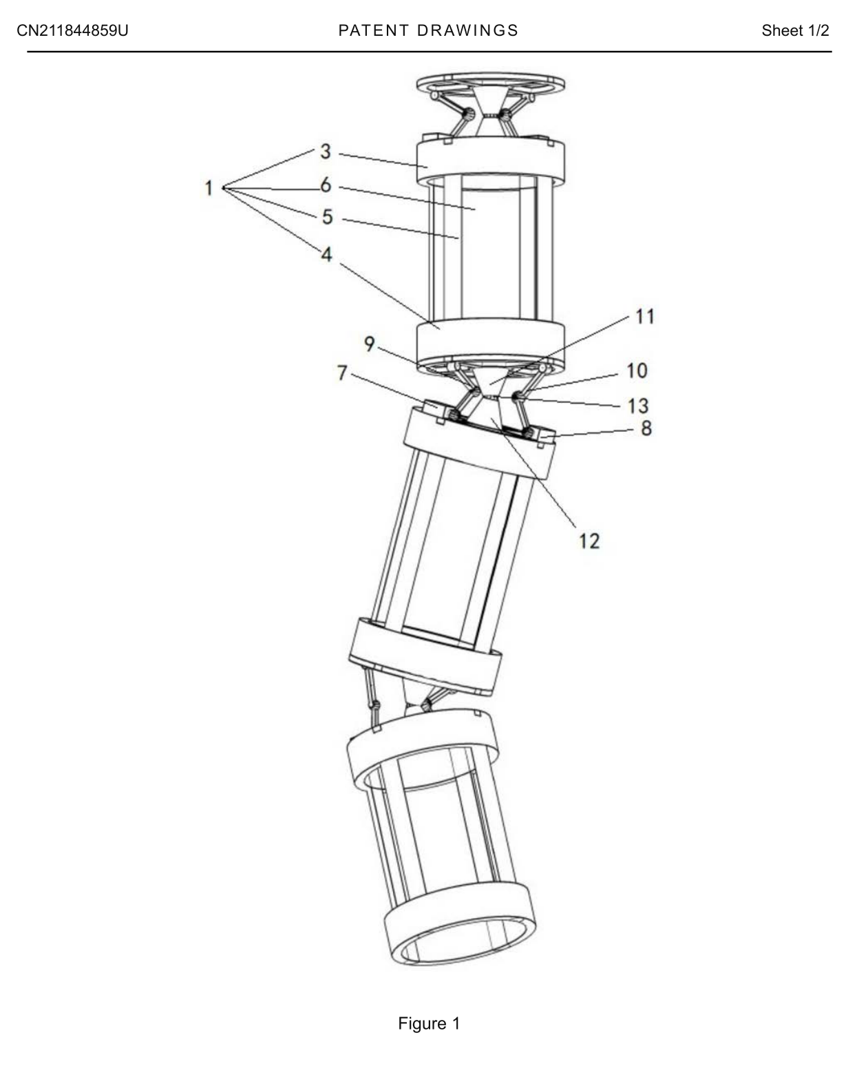
Figure 1 is a structural view of the main frame of the flexible unmanned underwater vehicle structure.
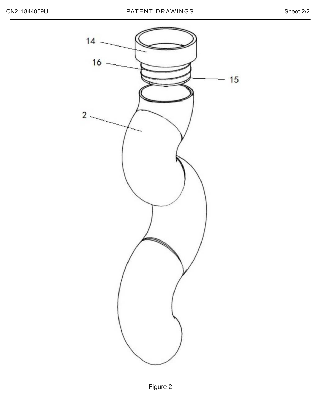
Figure 2 is a structural view of the flexible unmanned underwater vehicle structure.
Reference numerals: 1 — frame unit; 2 — waterproof enclosure; 3 — first mounting plate; 4 — second mounting plate; 5 — support rod; 6 — accommodation cavity; 7 — first steering device; 8 — second steering device; 9 — first universal-joint connecting rod; 10 — second universal-joint connecting rod; 11 — connecting seat; 12 — support seat; 13 — pivot shaft; 14 — clamping ring; 15 — joint seat; 16 — fastening thread.
Detailed embodiments
Specific embodiments of this utility model are described below with reference to the accompanying drawings. These descriptions assist understanding and do not limit the utility model. The technical features of the embodiments may be combined, provided that they do not conflict with one another.
As shown in the drawings, the flexible unmanned underwater vehicle structure comprises an extendable main frame that can bend and change shape, with a waterproof enclosure 2 fitted over it. The frame comprises multiple frame units 1 containing functional modules, connected end to end by steering structures. In this embodiment, the main frame is made of aluminium alloy. The frame unit 1 at the front of the vehicle may carry imaging equipment or connect to an external mission-payload compartment. The frame unit 1 at the rear contains a thruster module.
Preferably, frame unit 1 comprises a first mounting plate 3 and a second mounting plate 4 connected by several support rods 5. The plates 3 and 4 and rods 5 form an accommodation cavity 6.
Preferably, frame unit 1 has a cylindrical structure to improve underwater attitude and stability while reducing hydrodynamic resistance.
Preferably, the steering structure comprises a universal joint between adjacent frame units 1 to provide load-bearing support and allow angular movement in multiple directions. One frame unit carries a first steering device 7 and a second steering device 8, fitted respectively with a first universal-joint connecting rod 9 and a second universal-joint connecting rod 10. The other ends of both rods connect to the adjacent frame unit 1. Specifically, devices 7 and 8 are mounted on the first mounting plate 3 and connect through rods 9 and 10 to the second mounting plate 4 of the adjacent frame unit 1.
Preferably, the first steering device 7 and second steering device 8 are arranged at 90° to each other on frame unit 1, enabling adjustment in multiple directions.
Preferably, steering devices 7 and 8 have the same structure and are digital servos or hydraulic devices. An MCU control module drives each device according to a programmed motion, allowing the vehicle to change its bending configuration and the thruster to generate thrust in any direction. A single thruster at the rear is therefore sufficient for the vehicle to achieve various underwater navigation attitudes.
Preferably, the universal joint comprises a connecting seat 11 on one of two adjacent frame units 1 and a support seat 12 on the other. The connecting seat 11 is movably connected to the support seat 12. The joint provides both load-bearing support and angular movement in multiple directions. A pivot shaft 13 between the connecting seat 11 and support seat 12 enables their relative movement.
Preferably, sealing structures at both ends of the main frame seal the waterproof enclosure 2 and main frame. Each sealing structure comprises a clamping ring 14 and a joint seat 15 with fastening threads 16 on its outer wall. One end of seat 15 is mounted on the inner wall of ring 14 by threads 16; the other end is inserted into enclosure 2 and connected to the main frame. When imaging equipment is installed on the front frame unit 1, a sealing structure with a transparent window is selected. This window may be provided on clamping ring 14 and is not shown in the drawings.
In a preferred arrangement, waterproof enclosure 2 is a flexible hose enclosure with a wall thickness greater than 3 mm, made of high-pressure polyethylene or silicone. This can resist puncture and abrasive damage from external objects and withstand water pressure at depths of several tens of metres.
In a preferred arrangement, flow-guiding scales are provided on the outer surface of waterproof enclosure 2 to further improve the stability of the vehicle's underwater attitude.
Compared with the prior art, this utility model provides the following technical effects:
The structure improves the vehicle's flexibility for expansion and helps reduce maintenance costs. It also facilitates wider adoption, adaptation to more complex underwater environments and access to confined underwater terrain.
The foregoing describes preferred embodiments of this utility model and is not intended to limit it. Although the embodiments have been described in detail, a person skilled in the art may modify their technical solutions or replace some technical features with equivalent alternatives. Any modification, equivalent replacement or improvement within the spirit and principles of this utility model falls within its scope of protection.